What is Samarium Production – Definition

Samarium Production. For physicists and for reactor operators, it is important to understand the mechanisms that produce and remove samarium from the reactor. Periodic Table

Samarium Production and Removal

Samarium production and removalSamarium Production

Fission does not produce Sm 149 directly. The fission yield of samarium 149 is nearly zero. Sm-149 is in the decay chain of the the fission product neodymium 149, which decays to promethium 149. Because of the short half-life of Nd-149 (compared to the half-life of Pm-149), promethium may be considered as if it were formed directly from fission. The decay sequence is depicted on the figure.

Samarium Removal

An important difference between Xe-135 and Sm-149 is that samarium 149 is a stable isotope, and therefore remains in the core after shutdown. There are only two ways of samarium removal. One of these processes is the samarium burnup, when the reactor is at power operation. The rate of samarium burnup is dependent upon the neutron flux and the samarium 149 concentration (i.e. the reaction rate).

The second process is associated with refueling. During refueling usually one third or one quarter of the core is removed to spent fuel pool and replaced by fresh fuel assemblies, while the remainder is rearranged to a location in the core better suited to its remaining level of enrichment. Therefore refueling naturally leads to a decrease in the overall samarium content in the core.

Samarium 149 – Differential Equations

Assuming that fission does not produce Sm 149 directly, and neglecting the small amount of promethium burnup, allows the situation to be described as follows. The production and removal of samarium can be characterized by the following differential equations.

samarium - differential equations

 
References:
Nuclear and Reactor Physics:
  1. J. R. Lamarsh, Introduction to Nuclear Reactor Theory, 2nd ed., Addison-Wesley, Reading, MA (1983).
  2. J. R. Lamarsh, A. J. Baratta, Introduction to Nuclear Engineering, 3d ed., Prentice-Hall, 2001, ISBN: 0-201-82498-1.
  3. W. M. Stacey, Nuclear Reactor Physics, John Wiley & Sons, 2001, ISBN: 0- 471-39127-1.
  4. Glasstone, Sesonske. Nuclear Reactor Engineering: Reactor Systems Engineering, Springer; 4th edition, 1994, ISBN: 978-0412985317
  5. W.S.C. Williams. Nuclear and Particle Physics. Clarendon Press; 1 edition, 1991, ISBN: 978-0198520467
  6. G.R.Keepin. Physics of Nuclear Kinetics. Addison-Wesley Pub. Co; 1st edition, 1965
  7. Robert Reed Burn, Introduction to Nuclear Reactor Operation, 1988.
  8. U.S. Department of Energy, Nuclear Physics and Reactor Theory. DOE Fundamentals Handbook, Volume 1 and 2. January 1993.
  9. Paul Reuss, Neutron Physics. EDP Sciences, 2008. ISBN: 978-2759800414.

Advanced Reactor Physics:

  1. K. O. Ott, W. A. Bezella, Introductory Nuclear Reactor Statics, American Nuclear Society, Revised edition (1989), 1989, ISBN: 0-894-48033-2.
  2. K. O. Ott, R. J. Neuhold, Introductory Nuclear Reactor Dynamics, American Nuclear Society, 1985, ISBN: 0-894-48029-4.
  3. D. L. Hetrick, Dynamics of Nuclear Reactors, American Nuclear Society, 1993, ISBN: 0-894-48453-2.
  4. E. E. Lewis, W. F. Miller, Computational Methods of Neutron Transport, American Nuclear Society, 1993, ISBN: 0-894-48452-4.

See also:

Samarium

We hope, this article, Samarium Production, helps you. If so, give us a like in the sidebar. Main purpose of this website is to help the public to learn some interesting and important information about radiation and dosimeters.

What is Samarium 149 – Definition

Samarium 149 is an indirect product of U-235 fission. Samarium 149 has an significant impact on the operation of a nuclear reactor, since it has a very large neutron capture cross-section. Periodic Table

What is Samarium

Samarium is a naturally-occurring chemical element with atomic number 62 which means there are 62 protons and 62 electrons in the atomic structure. The chemical symbol for samarium is Sm. Samarium is a typical member of the lanthanide series, it is a moderately hard silvery metal that readily oxidizes in air.

Samarium was first discovered in 1879 by the French chemist Paul Émile Lecoq de Boisbaudran. The name samarium is after the mineral samarskite from which it was isolated. Although classified as a rare earth element, samarium is the 40th most abundant element in the Earth’s crust and is more common than such metals as tin.

Naturally occurring samarium consists of five stable isotopes, 144Sm (3.08%), 149Sm (13.82%), 150Sm (7.37%), 152Sm (26.74), 154Sm 22.74%), and two isotopes with very long half-life 147Sm (15.00%), 148Sm (11.25%). Therefore naturally-occurring samarium is slightly radioactive – about 128 Bq/g.

In nuclear industry, especially natural and artificial samarium 149 has an important impact on the operation of a nuclear reactor. Samarium 149 has a very large neutron capture cross-section (about 42,000 barns). Since natural samarium contains about 14% of 149Sm, it can be used as an absorbing material in control rods.

Samarium 149 is also an indirect product of U-235 fission. For physicists and for reactor operators, it is important to understand the mechanisms that produce and remove samarium from the reactor to predict how the reactor will respond following changes in power level.

 
Table of Neutron Poisons

Samarium 149

samarium 149 - cross-section
Samarium – 149. Neutron capture and total cross-sections.
Source: JANIS (Java-based Nuclear Data Information Software); The JEFF-3.1.1 Nuclear Data Library

As was written, samarium 149 has an significant impact on the operation of a nuclear reactor. Samarium 149 is an indirect product of U-235 fission and has a very large neutron capture cross-section (about 42,000 barns). It does not decay, since it is a stable isotope. Almost no samarium 149 results directly from fission (γSm =  10-12), but most comes from the decay chain, Nd-149 (β– decay, 1.73 hr; γNd = 1.09%) to Pm-149 (β– decay, 53.1 hr) to Sm-149 (stable). The instantaneous production rate of samarium-149 is dependent on the promethium-149 concentration and therefore on the local neutron flux history. On the other hand, the destruction rate of samarium-149 is also dependent on the instantaneous local neutron flux. Its significance is primarily caused by two factors:

  • its high capture cross-section, which is about 42,000 barns
  • its high total yield, which is about 1.08%

Neither the cross-section nor the yield is as big for this nuclide as for xenon 135, so the samarium reactivity effects are much smaller.

Table - yields - xenon, iodine, promethium
Table of total yields for various nuclei – thermal fission.

In a typical nuclear reactor fueled with uranium-235, the presence of 149Sm as an indirect fission product is very important in the power operation of a nuclear reactor. In contrast to xenon poisoning, at zero-power operation the presence of 149Sm may not be neglected, since its concentration is significant. Engineers and operators must perfectly know behaviour of a reactor with samarium. The presence of 149Sm is associated with the following operational issues:

  • Equilibrium Samarium
  • Response to Reactor Shutdown and Startup

To understand these issues, we have to perfectly understand the production and removal of samarium 149.

Samarium Production and Removal

Samarium production and removalSamarium Production

Fission does not produce Sm 149 directly. The fission yield of samarium 149 is nearly zero. Sm-149 is in the decay chain of the the fission product neodymium 149, which decays to promethium 149. Because of the short half-life of Nd-149 (compared to the half-life of Pm-149), promethium may be considered as if it were formed directly from fission. The decay sequence is depicted on the figure.

Samarium Removal

An important difference between Xe-135 and Sm-149 is that samarium 149 is a stable isotope, and therefore remains in the core after shutdown. There are only two ways of samarium removal. One of these processes is the samarium burnup, when the reactor is at power operation. The rate of samarium burnup is dependent upon the neutron flux and the samarium 149 concentration (i.e. the reaction rate).

The second process is associated with refueling. During refueling usually one third or one quarter of the core is removed to spent fuel pool and replaced by fresh fuel assemblies, while the remainder is rearranged to a location in the core better suited to its remaining level of enrichment. Therefore refueling naturally leads to a decrease in the overall samarium content in the core.

Samarium 149 – Differential Equations

Assuming that fission does not produce Sm 149 directly, and neglecting the small amount of promethium burnup, allows the situation to be described as follows. The production and removal of samarium can be characterized by the following differential equations.

samarium - differential equations

Samarium Equilibrium – Promethium Equilibrium

When the rate of production of promethium equals the rate of removal of promethium equilibrium exists. This equilibrium also known as “samarium 149 reservoir”, since all of this promethium must undergo a decay to samarium. In equilibrium, the promethium concentration remains constant and is designated NPm(eq). The following equation for the promethium equilibrium concentration can be determined from the preceding equation by setting the dNPm/dt =0.

promethium equilibrium - equation

Since the equilibrium promethium concentration is proportional to the fission reaction rate, it is also proportional to reactor power level.

When the rate of production of samarium equals the rate of removal, equilibrium exists also for samarium. The samarium concentration remains constant and is designated NSm(eq). The following equation for the samarium equilibrium concentration can be determined from the preceding equation by setting the dNSm/dt =0. For samarium to be in equilibrium, promethium must also be in equilibrium. Substituting the expression for equilibrium promethium concentration into the equation for equilibrium samarium results in the following equation:

samarium equilibrium - equation

This expression for equilibrium samarium 149 concentration during reactor operation illustrates that equilibrium samarium 149 concentration is independent of neutron flux and power level. It follows the time of saturation is dependent upon the neutron flux level. The equilibrium concentration usually produces negative reactivity (samarium worth) of about -600 pcm.

Response to Reactor Shutdown and Startup

After reactor shutdown, the neutron flux drops to zero and there remains no channel of removal of samarium. On the other hand, there is significant amount of accumulated promethium that decays to samarium, therefore the concentration of samarium increases to a new level. This buildup is dependent upon the neutron flux level before the shutdown(i.e. upon the promethium equilibrium).

The new equilibrium is reached in approximately 20 days, and since samarium 149 is stable, the concentration remains essentially constant during reactor outage. Samarium 149 does not peak as xenon-135 does, but increases slowly to a maximum value as shown in figure. As was written samarium can be removed from the core by refueling. During refueling usually one third or one quarter of the core is removed to spent fuel pool and replaced by fresh fuel assemblies (without samarium), while the remainder is rearranged to a location in the core better suited to its remaining level of enrichment. Therefore refueling naturally leads to a decrease in the overall samarium content in the core.

After reactor startup samarium concentration usually decreases as a result of samarium burnup and very slow decay of promethium. Similarly, transient changes in samarium on power level changes are very small compared to xenon, and change very slowly over a week or so. In each case, the samarium level returns to the same equilibrium value.

Although samarium-149 has a constant poisoning effect during long-term sustained operation, its behavior during initial startup and during post-shutdown and restart periods requires special considerations in reactor design.

samarium equilibrium

It was written, the samarium equilibrium is independent of the neutron flux level, therefore stationary samarium worth is independent as well. Note that, the promethium equilibrium, which determines especially the samarium peak concentration after shutdown, is flux dependent! The way of reactor shutdown must be taken into account in estimated critical conditions calculations and it can influence MTC at the beginning of the next cycle.

Moreover, especially high flux research reactors, must not be shut down suddenly. Sudden shutdown of a reactor with thermal flux of about 1019 neutrons/cm-2.s-1 can cause more than thirty times higher samarium poisoning as in PWRs. This can cause permanent poisoning and preclude any reactor startup. These reactors must lower the reactor power gradually in order to burn off as much samarium 149 as possible before shutdown.

Special reference: Paul Reuss, Neutron Physics. EDP Sciences, 2008. ISBN: 978-2759800414.

 
References:
Nuclear and Reactor Physics:
  1. J. R. Lamarsh, Introduction to Nuclear Reactor Theory, 2nd ed., Addison-Wesley, Reading, MA (1983).
  2. J. R. Lamarsh, A. J. Baratta, Introduction to Nuclear Engineering, 3d ed., Prentice-Hall, 2001, ISBN: 0-201-82498-1.
  3. W. M. Stacey, Nuclear Reactor Physics, John Wiley & Sons, 2001, ISBN: 0- 471-39127-1.
  4. Glasstone, Sesonske. Nuclear Reactor Engineering: Reactor Systems Engineering, Springer; 4th edition, 1994, ISBN: 978-0412985317
  5. W.S.C. Williams. Nuclear and Particle Physics. Clarendon Press; 1 edition, 1991, ISBN: 978-0198520467
  6. G.R.Keepin. Physics of Nuclear Kinetics. Addison-Wesley Pub. Co; 1st edition, 1965
  7. Robert Reed Burn, Introduction to Nuclear Reactor Operation, 1988.
  8. U.S. Department of Energy, Nuclear Physics and Reactor Theory. DOE Fundamentals Handbook, Volume 1 and 2. January 1993.
  9. Paul Reuss, Neutron Physics. EDP Sciences, 2008. ISBN: 978-2759800414.

Advanced Reactor Physics:

  1. K. O. Ott, W. A. Bezella, Introductory Nuclear Reactor Statics, American Nuclear Society, Revised edition (1989), 1989, ISBN: 0-894-48033-2.
  2. K. O. Ott, R. J. Neuhold, Introductory Nuclear Reactor Dynamics, American Nuclear Society, 1985, ISBN: 0-894-48029-4.
  3. D. L. Hetrick, Dynamics of Nuclear Reactors, American Nuclear Society, 1993, ISBN: 0-894-48453-2.
  4. E. E. Lewis, W. F. Miller, Computational Methods of Neutron Transport, American Nuclear Society, 1993, ISBN: 0-894-48452-4.

See also:

Reactor Operation

We hope, this article, Samarium 149, helps you. If so, give us a like in the sidebar. Main purpose of this website is to help the public to learn some interesting and important information about radiation and dosimeters.

What is Spatial Xenon Oscillation – Definition

Spatial Xenon Oscillations. Large thermal reactors with little flux coupling between regions may experience spatial power oscillations because of the non-uniform presence of xenon 135. Periodic Table

Spatial Xenon Oscillations
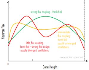
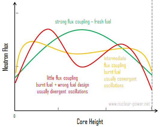
Spatial xenon oscillations - couplingLarge thermal reactors with little flux coupling between regions may experience spatial power oscillations because of the non-uniform presence of xenon 135. Xenon-induced spatial power oscillations occur as a result of rapid perturbations to power distribution that cause the xenon and iodine distribution to be out of phase with the perturbed power distribution. This results in a shift in xenon and iodine distributions that causes the power distribution to change in an opposite direction from the initial perturbation.

Xenon-135 is a product of U-235 fission and has a very large neutron capture cross section(about 2.6 x 10⁶ barns). It also decays radioactively with a half-life of 9.1 hours. Little of the Xe-135 results directly from fission, but most comes from the decay chain, Te-135 (β– decay, 0.5 min) to I-135 (β– decay, 6.6 hr) to Xe-135. The instantaneous production rate of xenon-135 is dependent on the iodine-135 concentration and therefore on the local neutron flux history. On the other hand, the destruction rate of xenon-135 is dependent on the instantaneous local neutron flux.

The combination of delayed generation and high neutron-capture cross section produces a diversity of impacts on nuclear reactor operation. The mechanism is described in the following four steps.

  1. An initial lack of symmetry (let say the axial symmetry in case of axial oscillations) in the core power distribution (for example as a result of significant control rods movement) causes an imbalance in fission rates within the reactor core, and therefore, in the iodine-135 buildup and the xenon-135 absorption.
  2. In the high-flux region, xenon-135 burnout allows the flux to increase further, while in the low-flux region, the increase in xenon-135 causes a further reduction in flux. The iodine concentration increases where the flux is high and decreases where the flux is low. This shift in the xenon distribution is such as to increase (decrease) the multiplication properties of the region in which the flux has increased (decreased), thus enhancing the flux tilt.
  3. As soon as the iodine-135 levels build up sufficiently, decay to xenon reverses the initial situation. Flux decreases in this area, and the former low-flux region increases in power.
  4. Repetition of these patterns can lead to xenon oscillations moving about the core with periods on the order of about 24 hours.

With little change in overall power level, these oscillations can change significantly the local power levels. This oscillation may go unnoticed and reach dangerous local flux levels if only the total power of the core is monitored. Therefore most PWRs use tandem power range excore neutron detectors to monitor upper and lower halves of the core separately.

Spatial xenon oscillations are typical for power reactors, since they operate at higher neutron fluxes, in which the xenon burnup becomes a very strong component of the xenon 135 dynamics. In order to sustain a significant xenon oscillation, the average thermal flux of the reactor should be greater than 1013 neutrons/cm-2.s-1 (typical PWR has about 3×10¹³ neutrons/cm-2.s-1). Together with the high flux, the reactor core should be large relative to the migration length such that the both halves of the core can be assumed to operate independently. Almost all PWRs meet these conditions. Consequently, they are vulnerable to xenon oscillations. Both the radial and axial dimensions of a commercial reactor are large enough to sustain xenon oscillations, however, the axial oscillations are the ones of major concern in most cases.

In a reactor system with strong negative temperature coefficients, the xenon 135 oscillations and with very high flux coupling are damped quite readily. This is one of reasons for designing reactors to have negative moderator temperature coefficients.

Since this effect influences global power distribution in the core, it also influences local power distribution. The problem, however, is in the initial swing of flux levels which displace the flux upward. Since at the higher elevations the local linear heat rate (FQ(z) limit) is highly restrictive, large xenon spatial oscillations have to be minimized to prevent exceeding FQ limits.

Spatial Xenon Oscillations Control
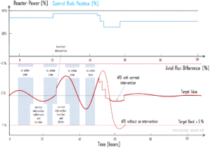
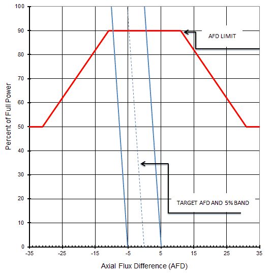
Xenon-induced spatial power oscillationsIn order to control xenon spatial oscillations, the axial flux difference or the axial offset are introduced. The most important of these are the axial flux difference (AFD) limits. AFD is a measure of the imbalance between the upper and lower halves of the core in terms of power or flux (ΔI). The AFD is determined  from the outputs of the upper and lower excore neutron detectors, which belong to so called the excore nuclear instrumentation system (NIS). AFD is controlled by control rods. The control rod banks can be inserted into the core from the top and therefore, a control rod bank motion will result in a symmetric reactivity insertion in the core in the radial and azimuthal directions, but the reactivity insertion will not be symmetric in the axial direction. As a result, a control rod bank insertion causes a  decrease in AFD since the power is shifted from the upper half to the lower half of the core. A proper intervention by control rods in proper time can lead to damp the oscillation.

There are different control schemes based on the availability of control mechanisms.  The most commonly used control mechanism of axial oscillations is based on Part Length Control Rods (PLCRs), which are moved around the central part of the core. A shift in AFD, either up or down, will then be controlled by moving the PLCRs in the proper direction. The rod control system automatically modulates the insertion of these control rods, which control the axial power distribution. These control rods are also called “grey” control rods. Grey control rods use a grey neutron absorber, which absorbs less neutrons than a “black” absorber.

If there are no PLCRs, the control strategy will be completely different. Additional control mechanisms are the inlet temperature, boron concentration in the reactor coolant, and positions of Full Length Control Rods. In any case, however, the strategy is quite simple and heuristic. The operator must respond to an oscillation with a sensible control action. The problem that must be solved is the quantification and the timing of this action. A method, which combines proper actions (insertion and withdrawal), is known as the Bang-Bang control.

Continued operation with a significant spatial xenon oscillation could lead, at least, to a reactor trip or, more seriously, to dangerously high local fuel temperatures. Even without such severe consequences, xenon oscillations causes an unnecessary temperature cycling that could lead to premature materials failure.

Axial Flux Difference

AFD is defined as:

AFD or ΔI = Itop – Ibottom

where Itop and Ibottom are expressed as a fraction of rated thermal power. As an example, assume the core is operating at 100% power. When the Itop = 49% and Ibottom = 51% the resulting ΔI = -2%. When the delta flux target is -5%. The core would then be able to operate with a delta flux of -10% to 0%. The + 5% and -5% flux difference around the target allows for a small amount of movement of the control rods.
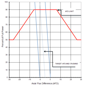
AFD - Axial Flux Difference - Axial Offset ControlDuring power operation, the AFD is maintained within the specified limits. Compliance with the AFD limits prevents a highly top- or bottom skewed axial power distribution. By limiting the amount of power distribution skewing, core peaking factors are consistent with the assumptions used in the safety analyses. Limiting power distribution skewing over time also minimizes the xenon distribution skewing, which is a significant factor in axial power distribution control.

The operating scheme used to control the axial power distribution involves maintaining the AFD within a tolerance band around a burnup dependent target, known as the target flux difference, to minimize the variation of the axial peaking factor and axial xenon distribution during unit maneuvers.

For plants operating with so called “constant axial offset control – CAOC”, the AFD limit involves a target band. This target band is, for example, +5% and -5% around the target value. Since the xenon concentration and distribution is flux and time dependent, the longer the core operates outside its target band, the greater the probability of initiating a xenon transient.

The target flux difference (ΔItarget) and its burnup dependent value is determined at equilibrium xenon conditions. The AFD is sensitive to many core related parameters such as control bank positions, core power level, axial burnup, axial xenon distribution and, to a lesser extent, reactor coolant temperature and boron concentrations.

Constant Axial Offset Control (CAOC) is a strategy, which is used to control axial power distribution in normal operation. CAOC requires that the AFD must be controlled within a narrow tolerance band around a burnup dependent target to minimize the probability of initiation xenon oscillations during power maneuvers. It also minimizes the variation of axial peaking factors.

Axial offset is defined as:

A/O = (Itop – Ibottom)/(Itop + Ibottom)

where Itop and Ibottom are expressed as a fraction of rated thermal power.

AFD and Safety Analyses

In summary, the AFD and the QPTR are direct and continuous measures of the core’s global power distribution. AFD measures global axial power distribution, whereas QPTR measures global azimuthal power distribution. Staying within their limits and proper operation of the control rods should maintain acceptable peaking factors (FQ(z) and FΔH) on a continuous basis. The AFD and QPTR limits ensure that peaking factors (FQ(z) and FΔH) remain below their limiting values by preventing an undetected change in the gross axial and radial power distribution.

Together, the LCO limits on the AFD, the QPTR, the rod insertion limits and the power distribution (i.e. the Heat Flux Hot Channel Factor (FQ(z)), the Nuclear Enthalpy Rise Hot Channel Factor (FNΔH)) are established to preclude core power distributions that exceed the safety analyses limits.

See also:

Xenon 135

We hope, this article, Spatial Xenon Oscillation, helps you. If so, give us a like in the sidebar. Main purpose of this website is to help the public to learn some interesting and important information about radiation and dosimeters.

What is Iodine Pit – Definition

Iodine Pit – Xenon Peak – Xenon Pit. This phenomenon is known as the “iodine pit” or “xenon pit” and it is particularly important near or at the end of the cycle (EOC). Periodic Table

Iodine Pit – Response to Reactor Shutdown

The most spectacular and well known phenomenon associated with xenon 135 is the behaviour of a reactor after a reactor shutdown. Recall, the proportion of 135I (6.6h) and 135Xe (9.2) half-lives is very important and determines these transients, especially those with power reduction, where the xenon buildup rate is higher than xenon decay.

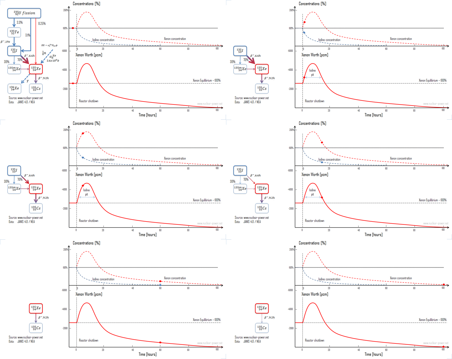
Consider the reactor shutdown from 100% to zero. Consider the reactor that is operated at 100% for a long time (i.e. iodine and xenon equilibria are established). At time t0, reactor power fall from 100% to 0% of rated power (e.g. after SCRAM). After shutdown, xenon 135 is no longer produced by fission and is no longer removed by burnup. The only remaining production mechanism is the decay of the iodine 135 which was in the core at the time of shutdown. The only removal mechanism for xenon 135 is decay. Therefore, when the reactor power is decreased, xenon concentration initially increases because the xenon burnup fall to zero and the 135I decay (6.6 h) is faster than the 135Xe decay (9.2 h).

The rate of the increase depends on the original neutron flux and increases with increasing flux. For large values of the neutron flux, the peak concentration occurs at 11.3 hours after shutdown (ln( λΙ/λXe)/( λI − λXe) ≈ 11.3 hours). The peak is reached when the product of the terms λΙNI is equal to λXeNXe. The amount of additional negative reactivity in the xenon peak is strongly dependent especially on the original neutron flux. For the reactor shutdown (LWRs) from 100% to zero the amount of additional negative reactivity may reach up to 2500 pcm, which has very important consequences. After reaching the xenon peak, the production of xenon from iodine decay is less than the removal of xenon by decay (λΙNI < λXeNXe), and the concentration of xenon 135 decreases. After another ten half-lives (from 11.3 hours to 80 hours), all the xenon undergo a beta decay. The decay of xenon 135 causes a continuous insertion of positive reactivity. This positive reactivity insertion must be taken into account in subcriticality maintenance (i.e. SDM) or when approaching to criticality. For LWRs, the xenon 135 concentration about 20 hours after shutdown from full power will be the same as the equilibrium xenon 135 concentration at full power. About 3 days after shutdown, the xenon 135 concentration will have decreased to a small percentage of its pre-shutdown level, and the reactor can be assumed to be xenon free without a significant error introduced into reactivity calculations.

An important consequence of this ‘xenon peak’ after a reactor shutdown is that, unless sufficient additional reactivity is present, it cannot be possible to restart the reactor again before many hours have passed. This phenomenon is known as the “iodine pit” or “xenon pit” and it is particularly important (LWRs) near or at the end of the cycle (EOC), since there is usually insufficient positive reactivity available from chemical shim. At the end of the cycle, the additional xenon reactivity (up to 2500 pcm) may provide sufficient negative reactivity to make the estimated critical conditions out of the allowed range, because there is insufficient positive reactivity available from control rod removal or chemical shim to counteract it. In another case, when there is sufficient reactivity to make a reactor critical, there need not be enough reactivity to increase reactor power (i.e. to balance power defect).

The inability of the reactor to be started due to the effects of xenon is sometimes referred to as a xenon precluded startup. It is of particular importance for reactors with very small excess reactivity (e.g. Heavy Water Reactors). The period of time where the reactor is unable to “override” the effects of xenon 135 is called “xenon dead time”.

Thermal power reactors are normally limited to flux levels of about 5 x 10¹³ neutrons/cm-2.s-1 so that timely restart can be ensured after shutdown. For reactors with very low thermal flux levels (~5 x 10¹³ neutrons/cm-2.s-1 or less), most xenon is removed by decay as opposed to xenon burnup. For these cases, reactor shutdown does not cause any xenon 135 peaking effect. Following the peak in xenon 135 concentration about 10 hours after shutdown, the xenon 135 concentration will decrease at a rate controlled by the decay of iodine 135 into xenon 135 and the decay rate of xenon 135.

Xenon pit - Iodine pit
Iodine Pit – Response to Reactor Shutdown

See also:

Xenon 135

We hope, this article, Iodine Pit, helps you. If so, give us a like in the sidebar. Main purpose of this website is to help the public to learn some interesting and important information about radiation and dosimeters.

What is Xenon Transient – Definition

Xenon Transients – Response to Reactor Power Changes. Here will be shown, iodine and xenon concentrations significantly differ with certain neutron flux level. Periodic Table

Xenon Transients – Response to Reactor Power Changes

As can be seen, iodine and xenon concentrations significantly differ with certain neutron flux level. Here, we will illustrate a typical xenon transient between different power levels. Recall, the proportion of 135I (6.6h) and 135Xe (9.2) half-lives is very important and determines these transients, especially those with power reduction, where the xenon buildup rate is higher than xenon decay.

Consider the power increase from 50% to 100% of rated power. Consider a reactor that is operated at 50% for a long time (i.e. iodine and xenon equilibria are established). At time t0, reactor power is raised from 50% to 100% of rated power. When the reactor power is increased, xenon concentration initially decreases because the burnup is increased due to higher reaction rate. Because 95% of the xenon production is from iodine 135 decay, which has a 6.6 hours half-life, the production of xenon remains constant for several hours. After a few hours (roughly 4 to 6 hours depending on power levels) the rate of production of xenon from iodine and fission equals the rate of removal of xenon by burnup and decay. At this point, the xenon concentration reaches a minimum. The xenon concentration then increases to the new equilibrium level for the new power level in roughly 40 to 50 hours. It should be noted that the magnitude and the rate of change of xenon concentration during the initial 4 to 6 hours following the power change is dependent upon the initial power level and on the amount of change in power level. The xenon concentration change is greater for a larger change in power level. For a power decrease the behaviour is reversed.

xenon transient - change in power

Iodine Pit – Response to Reactor Shutdown

The most spectacular and well known phenomenon associated with xenon 135 is the behaviour of a reactor after a reactor shutdown. Recall, the proportion of 135I (6.6h) and 135Xe (9.2) half-lives is very important and determines these transients, especially those with power reduction, where the xenon buildup rate is higher than xenon decay.

Consider the reactor shutdown from 100% to zero. Consider the reactor that is operated at 100% for a long time (i.e. iodine and xenon equilibria are established). At time t0, reactor power fall from 100% to 0% of rated power (e.g. after SCRAM). After shutdown, xenon 135 is no longer produced by fission and is no longer removed by burnup. The only remaining production mechanism is the decay of the iodine 135 which was in the core at the time of shutdown. The only removal mechanism for xenon 135 is decay. Therefore, when the reactor power is decreased, xenon concentration initially increases because the xenon burnup fall to zero and the 135I decay (6.6 h) is faster than the 135Xe decay (9.2 h).

The rate of the increase depends on the original neutron flux and increases with increasing flux. For large values of the neutron flux, the peak concentration occurs at 11.3 hours after shutdown (ln( λΙ/λXe)/( λI − λXe) ≈ 11.3 hours). The peak is reached when the product of the terms λΙNI is equal to λXeNXe. The amount of additional negative reactivity in the xenon peak is strongly dependent especially on the original neutron flux. For the reactor shutdown (LWRs) from 100% to zero the amount of additional negative reactivity may reach up to 2500 pcm, which has very important consequences. After reaching the xenon peak, the production of xenon from iodine decay is less than the removal of xenon by decay (λΙNI < λXeNXe), and the concentration of xenon 135 decreases. After another ten half-lives (from 11.3 hours to 80 hours), all the xenon undergo a beta decay. The decay of xenon 135 causes a continuous insertion of positive reactivity. This positive reactivity insertion must be taken into account in subcriticality maintenance (i.e. SDM) or when approaching to criticality. For LWRs, the xenon 135 concentration about 20 hours after shutdown from full power will be the same as the equilibrium xenon 135 concentration at full power. About 3 days after shutdown, the xenon 135 concentration will have decreased to a small percentage of its pre-shutdown level, and the reactor can be assumed to be xenon free without a significant error introduced into reactivity calculations.

An important consequence of this ‘xenon peak’ after a reactor shutdown is that, unless sufficient additional reactivity is present, it cannot be possible to restart the reactor again before many hours have passed. This phenomenon is known as the “iodine pit” or “xenon pit” and it is particularly important (LWRs) near or at the end of the cycle (EOC), since there is usually insufficient positive reactivity available from chemical shim. At the end of the cycle, the additional xenon reactivity (up to 2500 pcm) may provide sufficient negative reactivity to make the estimated critical conditions out of the allowed range, because there is insufficient positive reactivity available from control rod removal or chemical shim to counteract it. In another case, when there is sufficient reactivity to make a reactor critical, there need not be enough reactivity to increase reactor power (i.e. to balance power defect).

The inability of the reactor to be started due to the effects of xenon is sometimes referred to as a xenon precluded startup. It is of particular importance for reactors with very small excess reactivity (e.g. Heavy Water Reactors). The period of time where the reactor is unable to “override” the effects of xenon 135 is called “xenon dead time”.

Thermal power reactors are normally limited to flux levels of about 5 x 10¹³ neutrons/cm-2.s-1 so that timely restart can be ensured after shutdown. For reactors with very low thermal flux levels (~5 x 10¹³ neutrons/cm-2.s-1 or less), most xenon is removed by decay as opposed to xenon burnup. For these cases, reactor shutdown does not cause any xenon 135 peaking effect. Following the peak in xenon 135 concentration about 10 hours after shutdown, the xenon 135 concentration will decrease at a rate controlled by the decay of iodine 135 into xenon 135 and the decay rate of xenon 135.

Xenon pit - Iodine pit
Iodine Pit – Response to Reactor Shutdown

See also:

Xenon 135

We hope, this article, Xenon Transient, helps you. If so, give us a like in the sidebar. Main purpose of this website is to help the public to learn some interesting and important information about radiation and dosimeters.

What is Equilibrium Xenon – Stationary Xenon Poisoning – Definition

Equilibrium Xenon – Stationary Xenon Poisoning. When the rate of production of xenon 135 equals the rate of removal, equilibrium exists also for xenon. Periodic Table

Equilibrium Xenon – Stationary Xenon Poisoning

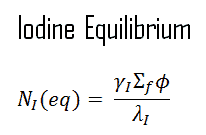
When the rate of production of iodine equals the rate of removal of iodine, equilibrium exists. This equilibrium also known as “xenon 135 reservoir”, since all of this iodine must undergo a decay to xenon. In equilibrium, the iodine concentration remains constant and is designated NI(eq). The following equation for the iodine equilibrium concentration can be determined from the preceding equation by setting the dNI/dt =0. Since the equilibrium iodine concentration is proportional to the fission reaction rate, it is also proportional to reactor power level.

When the rate of production of xenon 135 equals the rate of removal, equilibrium exists also for xenon. The xenon concentration remains constant and is designated NXe(eq). The following equation (1) for the xenon equilibrium concentration can be determined from the preceding equation by setting the dNXe/dt =0. For xenon 135 to be in equilibrium, iodine 135 must also be in equilibrium. Substituting the expression for equilibrium iodine 135 concentration into the equation for equilibrium xenon (1) results in the following (2).

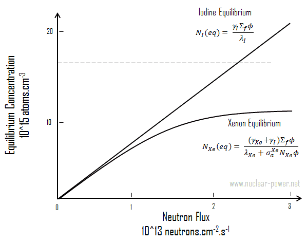
From this equation it can be seen that the equilibrium value for xenon 135 increases as power increases, because the numerator is proportional to the fission reaction rate. But the thermal flux is also in the denominator. Therefore, as the thermal flux exceeds some value, the xenon burnup begins to dominate, and at approximately 1015 neutrons.cm-2.s-1, the xenon-135 concentration approaches a limiting value. The equilibrium iodine 135 and xenon 135 concentrations as a function of neutron flux are illustrated in the following figure.

Xenon 135 Worth after Reactor Startup

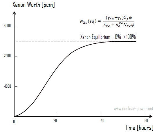
Following reactor startup both iodine and xenon concentrations build from zero to equilibrium values over a period of several half-lives (e.g. seven half-lives). Since the half-lives are in hours, after a few days (in about 40 to 50 hours.) equilibrium is achieved. This is known as the stationary xenon poisoning. In pressurized water reactors, this stationary xenon poisoning reaches up to 2500 pcm and the excess reactivity must be able to compensate equilibrium xenon, when the reactor is operated at nominal power. Stationary xenon poisoning usually does not vary with cycle burnup, but differs significantly with the reactor power level.

iodine equilibrium - equation

xenon equilibrium - equations

xenon equilibrium - iodine equilibrium

Xenon Worth after reactor startup
Xenon 135 worth after reactor startup.

Equilibrium xenon for different power levels

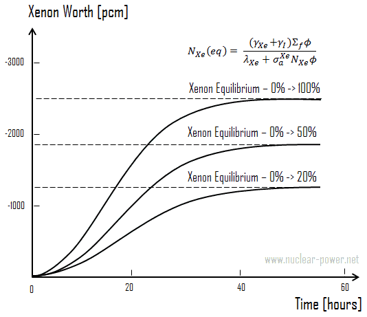
Xenon Worth - different power levelsAs was shown, the equilibrium iodine 135 and xenon 135 concentrations are a function of neutron flux.The higher the neutron flux the higher the equilibrium xenon 135 concentration, but equilibrium xenon-135 is not directly proportional to neutron flux level (due to an increase in burnup rate). For example, equilibrium xenon 135 at 20% power is about half the value for equilibrium xenon 135 at 100% power for many reactors.

Because the xenon 135 concentration directly affects the reactivity level in the reactor core, the negative reactivity due to the xenon concentrations, known as the xenon worth, for different power levels or conditions are frequently plotted instead of the xenon concentration.

See also:

Xenon 135

We hope, this article, Equilibrium Xenon – Stationary Xenon Poisoning, helps you. If so, give us a like in the sidebar. Main purpose of this website is to help the public to learn some interesting and important information about radiation and dosimeters.

What is Xenon 135 – Differential Equations – Definition

Xenon 135 – Differential Equations. The production and removal of xenon 135 can be characterized by the following differential equations:

Xenon 135 – Differential Equations

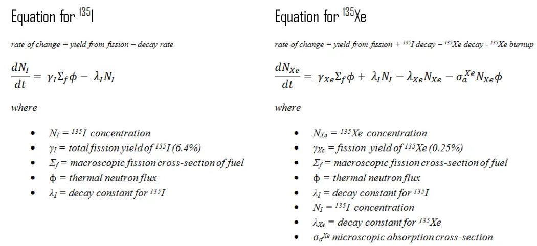
The production and removal of xenon can be characterized by the following differential equations:

xenon 135 - iodine 135 - equations

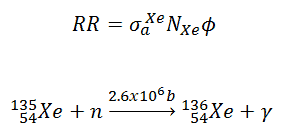
Note the coupling between the two equations. Decay of iodine 135, λINI, in equation for iodine produces xenon in the equation for xenon. As can be seen, we have neglected the burnup of 135I, since its cross-section is very small. The xenon burnup term above refers to neutron absorption (or neutron capture) by xenon 135 by the following reaction. Xenon 136 is not a significant neutron absorber. Therefore, the neutron absorption by xenon 135 constitutes removal of poison from the reactor. The burnup rate of xenon 135 is dependent upon the neutron flux and the xenon 135 concentration (i.e. the reaction rate).

xenon - 135 - neutron capture

See also:

Xenon 135

We hope, this article, Xenon 135 – Differential Equations, helps you. If so, give us a like in the sidebar. Main purpose of this website is to help the public to learn some interesting and important information about radiation and dosimeters.

What is Iodine 135 – Definition

Iodine 135. The instantaneous production rate of xenon-135 is dependent on the iodine-135 concentration and therefore on the local neutron flux history. Periodic Table

Iodine 135

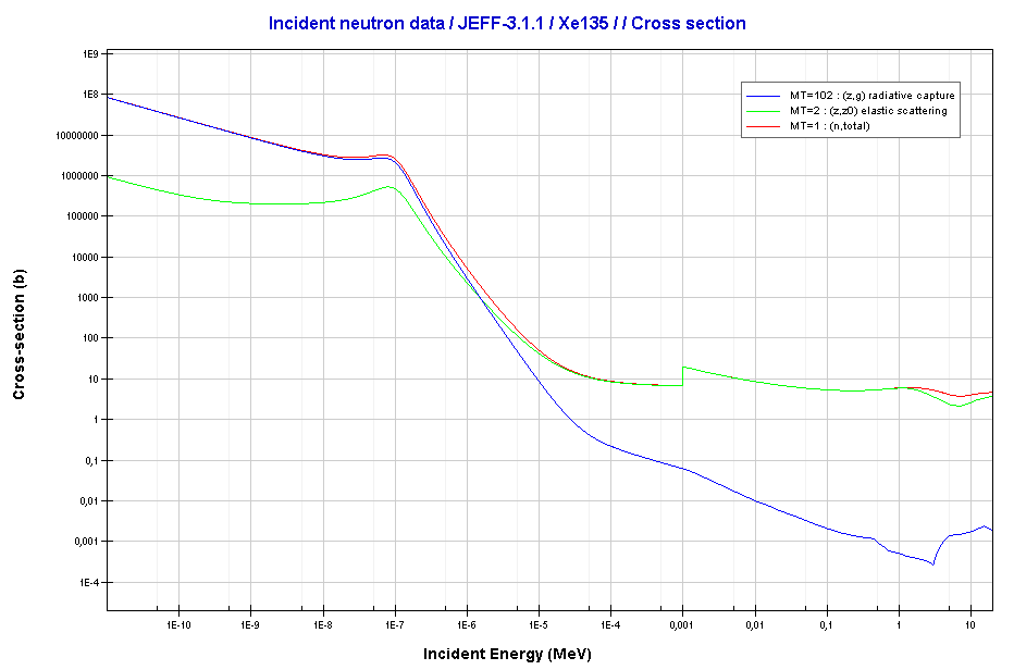
Xenon - 135. Neutron absorption and scattering. Comparison of cross-sections.
Xenon – 135. Neutron absorption and scattering. Comparison of cross-sections.
Source: JANIS (Java-based Nuclear Data Information Software); The JEFF-3.1.1 Nuclear Data Library

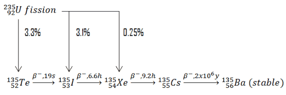
As was written, xenon 135 has a tremendous impact on the operation of a nuclear reactor. Xenon-135 is a product of U-235 fission and has a very large neutron capture cross-section (about 2.6 x 10⁶ barns). It also decays radioactively with a half-life of 9.1 hours. Little of the Xe-135 results directly from fission, but most comes from the decay chain, Te-135 (β– decay, 19 sec) to I-135 (β– decay, 6.6 hr) to Xe-135. The instantaneous production rate of xenon 135 is dependent on the iodine 135 concentration and therefore on the local neutron flux history. On the other hand, the destruction rate of xenon 135 is dependent on the instantaneous local neutron flux. Its significance is primarily caused by two factors:

  • its enormous capture cross-section
  • its ultimate total yield, which is about 6.3%

In a typical nuclear reactor fueled with uranium 235, the presence of 135Xe as a fission product is of the highest importance in the power operation. At zero-power operation the presence of 135Xe may be neglected, since its concentration is very low. At power operation the situation is different.

Engineers and operators must perfectly know behaviour of a reactor with xenon 135. They are trained to properly anticipate and react to the transients induced by equilibrium or non-equilibrium xenon distribution. The presence of 135Xe is associated with the following operational issues:

  • Equilibrium Xenon – Xenon Poisoning
  • Equilibrium Xenon for Different Power Levels
  • Response to Reactor Power Changes
  • Iodine Pit – Response to Reactor Shutdown
  • Spatial Xenon Oscillations

To understand these issues, we have to perfectly understand the production and removal of xenon 135.

Production and Removal of Xenon 135

 
Table of total yields for various nuclei - thermal fission
Table - yields - xenon, iodine, promethium
Table of total yields for various nuclei – thermal fission.

Equilibrium Iodine

When the rate of production of iodine equals the rate of removal of iodine, equilibrium exists. This equilibrium also known as “xenon 135 reservoir”, since all of this iodine must undergo a decay to xenon. In equilibrium, the iodine concentration remains constant and is designated NI(eq). The following equation for the iodine equilibrium concentration can be determined from the preceding equation by setting the dNI/dt =0. Since the equilibrium iodine concentration is proportional to the fission reaction rate, it is also proportional to reactor power level.
iodine equilibrium - equation

See also:

Xenon 135

We hope, this article, Iodine 135, helps you. If so, give us a like in the sidebar. Main purpose of this website is to help the public to learn some interesting and important information about radiation and dosimeters.

What is Xenon – Definition

What is Xenon – Xe Element. Xenon is a naturally-occurring chemical element with atomic number 54 which means there are 54 protons and 54 electrons in the atomic structure. Periodic Table

What is Xenon

What is Xenon – Xe Element

Xenon is a naturally-occurring chemical element with atomic number 54 which means there are 54 protons and 54 electrons in the atomic structure. The chemical symbol for xenon is Xe. Xenon is a colorless, dense, odorless noble gas found in the Earth’s atmosphere in trace amounts.

Xenon was first discovered in 1898 by the Scottish chemist William Ramsay and English chemist Morris Travers. The name xenon for this gas comes from the Greek word ξένον [xenon], neuter singular form of ξένος [xenos], meaning ‘foreign(er)’, ‘strange(r)’, or ‘guest’.

Natural xenon consists of eight stable isotopes, 124Xe (0.095%), 126Xe (0.089%), 128Xe (1.91%), 129Xe (26.4%), 130Xe (4.07%), 131Xe (21.23%), 132Xe (26.91%),  134Xe (10.44%), and one isotope with very long half-life 136Xe (8.86%).

In nuclear industry, especially artificial xenon 135 has a tremendous impact on the operation of a nuclear reactor. For physicists and for reactor operators, it is important to understand the mechanisms that produce and remove xenon from the reactor to predict how the reactor will respond following changes in power level.

Another important isotope is the xenon 133, which has half-life of 5.2 days, and its presence in a reactor coolant indicates (together with xenon 135) a possible failure of fuel cladding. A new defect will often result in a step increase in only the Xe-133 activity, which is measured from reactor coolant. As the defect enlarges, the release rate of the soluble, longer-lived nuclides, particularly I-131, I-134, Cs-134, and Cs-137 will increase.

See also:

Xenon 135

We hope, this article, Xenon, helps you. If so, give us a like in the sidebar. Main purpose of this website is to help the public to learn some interesting and important information about radiation and dosimeters.

What is Xenon 135 – Definition

Xenon-135 is a product of U-235 fission and has a very large neutron capture cross-section (about 2.6 x 10^6 barns). Xenon 135 decays with a half-life of 9.1 hours. Periodic Table

What is Xenon

Xenon is a naturally-occurring chemical element with atomic number 54 which means there are 54 protons and 54 electrons in the atomic structure. The chemical symbol for xenon is Xe. Xenon is a colorless, dense, odorless noble gas found in the Earth’s atmosphere in trace amounts.

Xenon was first discovered in 1898 by the Scottish chemist William Ramsay and English chemist Morris Travers. The name xenon for this gas comes from the Greek word ξένον [xenon], neuter singular form of ξένος [xenos], meaning ‘foreign(er)’, ‘strange(r)’, or ‘guest’.

Natural xenon consists of eight stable isotopes, 124Xe (0.095%), 126Xe (0.089%), 128Xe (1.91%), 129Xe (26.4%), 130Xe (4.07%), 131Xe (21.23%), 132Xe (26.91%),  134Xe (10.44%), and one isotope with very long half-life 136Xe (8.86%).

In nuclear industry, especially artificial xenon 135 has a tremendous impact on the operation of a nuclear reactor. For physicists and for reactor operators, it is important to understand the mechanisms that produce and remove xenon from the reactor to predict how the reactor will respond following changes in power level.

Another important isotope is the xenon 133, which has half-life of 5.2 days, and its presence in a reactor coolant indicates (together with xenon 135) a possible failure of fuel cladding. A new defect will often result in a step increase in only the Xe-133 activity, which is measured from reactor coolant. As the defect enlarges, the release rate of the soluble, longer-lived nuclides, particularly I-131, I-134, Cs-134, and Cs-137 will increase.

Xenon 135

Xenon - 135. Neutron absorption and scattering. Comparison of cross-sections.
Xenon – 135. Neutron absorption and scattering. Comparison of cross-sections.
Source: JANIS (Java-based Nuclear Data Information Software); The JEFF-3.1.1 Nuclear Data Library

As was written, xenon 135 has a tremendous impact on the operation of a nuclear reactor. Xenon-135 is a product of U-235 fission and has a very large neutron capture cross-section (about 2.6 x 10⁶ barns). It also decays radioactively with a half-life of 9.1 hours. Little of the Xe-135 results directly from fission, but most comes from the decay chain, Te-135 (β– decay, 19 sec) to I-135 (β– decay, 6.6 hr) to Xe-135. The instantaneous production rate of xenon 135 is dependent on the iodine 135 concentration and therefore on the local neutron flux history. On the other hand, the destruction rate of xenon 135 is dependent on the instantaneous local neutron flux. Its significance is primarily caused by two factors:

  • its enormous capture cross-section
  • its ultimate total yield, which is about 6.3%

In a typical nuclear reactor fueled with uranium 235, the presence of 135Xe as a fission product is of the highest importance in the power operation. At zero-power operation the presence of 135Xe may be neglected, since its concentration is very low. At power operation the situation is different.

Engineers and operators must perfectly know behaviour of a reactor with xenon 135. They are trained to properly anticipate and react to the transients induced by equilibrium or non-equilibrium xenon distribution. The presence of 135Xe is associated with the following operational issues:

  • Equilibrium Xenon – Xenon Poisoning
  • Equilibrium Xenon for Different Power Levels
  • Response to Reactor Power Changes
  • Iodine Pit – Response to Reactor Shutdown
  • Spatial Xenon Oscillations

To understand these issues, we have to perfectly understand the production and removal of xenon 135.

Production and Removal of Xenon 135

 
Table of total yields for various nuclei - thermal fission
Table - yields - xenon, iodine, promethium
Table of total yields for various nuclei – thermal fission.

Production and Removal of Xenon 135

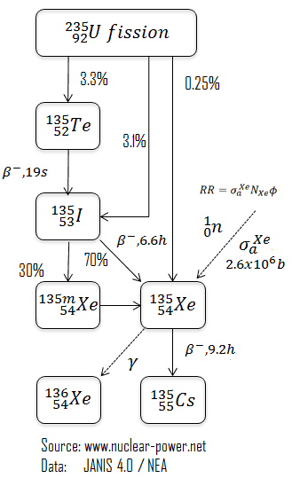
xenon 135 - reactions - decayIn general, there are two ways of xenon 135 production in the reactor:

  • Decay of 135I. Most of xenon 135 is produced by beta decay of 135I (γI,total = 6.4%). In fact, the 135I is a direct fission product (γI = 3.1%) and a decay product of tellurium 135 (γTe = 3.3%), but the half-life of tellurium 135 is so short (~ 19 sec), that iodine-135 can be considered as the primary fission product. The fission yield (γ) for tellurium 135 is about 3.3%. Iodine 135 is not a strong neutron absorber, but decays to form the neutron poison xenon 135. About 95% of all the xenon 135 produced comes from the decay of iodine 135. Therefore, the half-life of iodine 135 plays an important role in the amount of xenon-135 present. The instantaneous production rate of xenon-135 is dependent on the iodine-135 concentration and therefore on the local neutron flux history.
  • Direct fission product. Xenon 135 is partly formed directly during fission. The fission yield (γXe) for xenon 135 is about 0.25%.

In general, there are two ways of xenon 135 removal from the reactor:

  • Decay of 135Xe. Xenon 135 decay via beta minus decay with half-life of 9.2 hours. The proportion of 135I and 135Xe half-lives is very important and determines transients, especially those with power reduction, where the xenon buildup rate is higher than xenon decay.
  • Xenon burnup. Since xenon 135 has very high neutron capture cross-section, it is significantly removed by neutron capture at significant neutron flux levels. The xenon burnup is determined by reaction rate:reaction rate - xenon 135 - reaction

Xenon 135 – Differential Equations

The production and removal of xenon can be characterized by the following differential equations:

xenon 135 - iodine 135 - equations

Note the coupling between the two equations. Decay of iodine 135, λINI, in equation for iodine produces xenon in the equation for xenon. As can be seen, we have neglected the burnup of 135I, since its cross-section is very small. The xenon burnup term above refers to neutron absorption (or neutron capture) by xenon 135 by the following reaction. Xenon 136 is not a significant neutron absorber. Therefore, the neutron absorption by xenon 135 constitutes removal of poison from the reactor. The burnup rate of xenon 135 is dependent upon the neutron flux and the xenon 135 concentration (i.e. the reaction rate).

xenon - 135 - neutron capture

Equilibrium Xenon – Stationary Xenon Poisoning

When the rate of production of iodine equals the rate of removal of iodine, equilibrium exists. This equilibrium also known as “xenon 135 reservoir”, since all of this iodine must undergo a decay to xenon. In equilibrium, the iodine concentration remains constant and is designated NI(eq). The following equation for the iodine equilibrium concentration can be determined from the preceding equation by setting the dNI/dt =0. Since the equilibrium iodine concentration is proportional to the fission reaction rate, it is also proportional to reactor power level.

When the rate of production of xenon 135 equals the rate of removal, equilibrium exists also for xenon. The xenon concentration remains constant and is designated NXe(eq). The following equation (1) for the xenon equilibrium concentration can be determined from the preceding equation by setting the dNXe/dt =0. For xenon 135 to be in equilibrium, iodine 135 must also be in equilibrium. Substituting the expression for equilibrium iodine 135 concentration into the equation for equilibrium xenon (1) results in the following (2).

From this equation it can be seen that the equilibrium value for xenon 135 increases as power increases, because the numerator is proportional to the fission reaction rate. But the thermal flux is also in the denominator. Therefore, as the thermal flux exceeds some value, the xenon burnup begins to dominate, and at approximately 1015 neutrons.cm-2.s-1, the xenon-135 concentration approaches a limiting value. The equilibrium iodine 135 and xenon 135 concentrations as a function of neutron flux are illustrated in the following figure.

Xenon 135 Worth after Reactor Startup

Following reactor startup both iodine and xenon concentrations build from zero to equilibrium values over a period of several half-lives (e.g. seven half-lives). Since the half-lives are in hours, after a few days (in about 40 to 50 hours.) equilibrium is achieved. This is known as the stationary xenon poisoning. In pressurized water reactors, this stationary xenon poisoning reaches up to 2500 pcm and the excess reactivity must be able to compensate equilibrium xenon, when the reactor is operated at nominal power. Stationary xenon poisoning usually does not vary with cycle burnup, but differs significantly with the reactor power level.

iodine equilibrium - equation

xenon equilibrium - equations

xenon equilibrium - iodine equilibrium

Xenon Worth after reactor startup
Xenon 135 worth after reactor startup.

Equilibrium xenon for different power levels

Xenon Worth - different power levelsAs was shown, the equilibrium iodine 135 and xenon 135 concentrations are a function of neutron flux.The higher the neutron flux the higher the equilibrium xenon 135 concentration, but equilibrium xenon-135 is not directly proportional to neutron flux level (due to an increase in burnup rate). For example, equilibrium xenon 135 at 20% power is about half the value for equilibrium xenon 135 at 100% power for many reactors.

Because the xenon 135 concentration directly affects the reactivity level in the reactor core, the negative reactivity due to the xenon concentrations, known as the xenon worth, for different power levels or conditions are frequently plotted instead of the xenon concentration.

Response to Reactor Power Changes

As can be seen, iodine and xenon concentrations significantly differ with certain neutron flux level. Here, we will illustrate a typical xenon transient between different power levels. Recall, the proportion of 135I (6.6h) and 135Xe (9.2) half-lives is very important and determines these transients, especially those with power reduction, where the xenon buildup rate is higher than xenon decay.

Consider the power increase from 50% to 100% of rated power. Consider a reactor that is operated at 50% for a long time (i.e. iodine and xenon equilibria are established). At time t0, reactor power is raised from 50% to 100% of rated power. When the reactor power is increased, xenon concentration initially decreases because the burnup is increased due to higher reaction rate. Because 95% of the xenon production is from iodine 135 decay, which has a 6.6 hours half-life, the production of xenon remains constant for several hours. After a few hours (roughly 4 to 6 hours depending on power levels) the rate of production of xenon from iodine and fission equals the rate of removal of xenon by burnup and decay. At this point, the xenon concentration reaches a minimum. The xenon concentration then increases to the new equilibrium level for the new power level in roughly 40 to 50 hours. It should be noted that the magnitude and the rate of change of xenon concentration during the initial 4 to 6 hours following the power change is dependent upon the initial power level and on the amount of change in power level. The xenon concentration change is greater for a larger change in power level. For a power decrease the behaviour is reversed.

xenon transient - change in power

Iodine Pit – Response to Reactor Shutdown

The most spectacular and well known phenomenon associated with xenon 135 is the behaviour of a reactor after a reactor shutdown. Recall, the proportion of 135I (6.6h) and 135Xe (9.2) half-lives is very important and determines these transients, especially those with power reduction, where the xenon buildup rate is higher than xenon decay.

Consider the reactor shutdown from 100% to zero. Consider the reactor that is operated at 100% for a long time (i.e. iodine and xenon equilibria are established). At time t0, reactor power fall from 100% to 0% of rated power (e.g. after SCRAM). After shutdown, xenon 135 is no longer produced by fission and is no longer removed by burnup. The only remaining production mechanism is the decay of the iodine 135 which was in the core at the time of shutdown. The only removal mechanism for xenon 135 is decay. Therefore, when the reactor power is decreased, xenon concentration initially increases because the xenon burnup fall to zero and the 135I decay (6.6 h) is faster than the 135Xe decay (9.2 h).

The rate of the increase depends on the original neutron flux and increases with increasing flux. For large values of the neutron flux, the peak concentration occurs at 11.3 hours after shutdown (ln( λΙ/λXe)/( λI − λXe) ≈ 11.3 hours). The peak is reached when the product of the terms λΙNI is equal to λXeNXe. The amount of additional negative reactivity in the xenon peak is strongly dependent especially on the original neutron flux. For the reactor shutdown (LWRs) from 100% to zero the amount of additional negative reactivity may reach up to 2500 pcm, which has very important consequences. After reaching the xenon peak, the production of xenon from iodine decay is less than the removal of xenon by decay (λΙNI < λXeNXe) , and the concentration of xenon 135 decreases. After another ten half-lives (from 11.3 hours to 80 hours), all the xenon undergo a beta decay. The decay of xenon 135 causes a continuous insertion of positive reactivity. This positive reactivity insertion must be taken into account in subcriticality maintenance (i.e. SDM) or when approaching to criticality. For LWRs, the xenon 135 concentration about 20 hours after shutdown from full power will be the same as the equilibrium xenon 135 concentration at full power. About 3 days after shutdown, the xenon 135 concentration will have decreased to a small percentage of its pre-shutdown level, and the reactor can be assumed to be xenon free without a significant error introduced into reactivity calculations.

An important consequence of this ‘xenon peak’ after a reactor shutdown is that, unless sufficient additional reactivity is present, it cannot be possible to restart the reactor again before many hours have passed. This phenomenon is known as the “iodine pit” or “xenon pit” and it is particularly important (LWRs) near or at the end of the cycle (EOC), since there is usually insufficient positive reactivity available from chemical shim. At the end of the cycle, the additional xenon reactivity (up to 2500 pcm) may provide sufficient negative reactivity to make the estimated critical conditions out of the allowed range, because there is insufficient positive reactivity available from control rod removal or chemical shim to counteract it. In another case, when there is sufficient reactivity to make a reactor critical, there need not be enough reactivity to increase reactor power (i.e. to balance power defect).

The inability of the reactor to be started due to the effects of xenon is sometimes referred to as a xenon precluded startup. It is of particular importance for reactors with very small excess reactivity (e.g. Heavy Water Reactors). The period of time where the reactor is unable to “override” the effects of xenon 135 is called “xenon dead time”.

Thermal power reactors are normally limited to flux levels of about 5 x 10¹³ neutrons/cm-2.s-1 so that timely restart can be ensured after shutdown. For reactors with very low thermal flux levels (~5 x 10¹³ neutrons/cm-2.s-1 or less), most xenon is removed by decay as opposed to xenon burnup. For these cases, reactor shutdown does not cause any xenon 135 peaking effect. Following the peak in xenon 135 concentration about 10 hours after shutdown, the xenon 135 concentration will decrease at a rate controlled by the decay of iodine 135 into xenon 135 and the decay rate of xenon 135.

Xenon pit - Iodine pit
Iodine Pit – Response to Reactor Shutdown

Spatial Xenon Oscillations

Spatial xenon oscillations - couplingLarge thermal reactors with little flux coupling between regions may experience spatial power oscillations because of the non-uniform presence of xenon 135. Xenon-induced spatial power oscillations occur as a result of rapid perturbations to power distribution that cause the xenon and iodine distribution to be out of phase with the perturbed power distribution. This results in a shift in xenon and iodine distributions that causes the power distribution to change in an opposite direction from the initial perturbation.

Xenon-135 is a product of U-235 fission and has a very large neutron capture cross section(about 2.6 x 10⁶ barns). It also decays radioactively with a half-life of 9.1 hours. Little of the Xe-135 results directly from fission, but most comes from the decay chain, Te-135 (β– decay, 0.5 min) to I-135 (β– decay, 6.6 hr) to Xe-135. The instantaneous production rate of xenon-135 is dependent on the iodine-135 concentration and therefore on the local neutron flux history. On the other hand, the destruction rate of xenon-135 is dependent on the instantaneous local neutron flux.

The combination of delayed generation and high neutron-capture cross section produces a diversity of impacts on nuclear reactor operation. The mechanism is described in the following four steps.

  1. An initial lack of symmetry (let say the axial symmetry in case of axial oscillations) in the core power distribution (for example as a result of significant control rods movement) causes an imbalance in fission rates within the reactor core, and therefore, in the iodine-135 buildup and the xenon-135 absorption.
  2. In the high-flux region, xenon-135 burnout allows the flux to increase further, while in the low-flux region, the increase in xenon-135 causes a further reduction in flux. The iodine concentration increases where the flux is high and decreases where the flux is low. This shift in the xenon distribution is such as to increase (decrease) the multiplication properties of the region in which the flux has increased (decreased), thus enhancing the flux tilt.
  3. As soon as the iodine-135 levels build up sufficiently, decay to xenon reverses the initial situation. Flux decreases in this area, and the former low-flux region increases in power.
  4. Repetition of these patterns can lead to xenon oscillations moving about the core with periods on the order of about 24 hours.

With little change in overall power level, these oscillations can change significantly the local power levels. This oscillation may go unnoticed and reach dangerous local flux levels if only the total power of the core is monitored. Therefore most PWRs use tandem power range excore neutron detectors to monitor upper and lower halves of the core separately.

Spatial xenon oscillations are typical for power reactors, since they operate at higher neutron fluxes, in which the xenon burnup becomes a very strong component of the xenon 135 dynamics. In order to sustain a significant xenon oscillation, the average thermal flux of the reactor should be greater than 1013 neutrons/cm-2.s-1 (typical PWR has about 3×10¹³ neutrons/cm-2.s-1). Together with the high flux, the reactor core should be large relative to the migration length such that the both halves of the core can be assumed to operate independently. Almost all PWRs meet these conditions. Consequently, they are vulnerable to xenon oscillations. Both the radial and axial dimensions of a commercial reactor are large enough to sustain xenon oscillations, however, the axial oscillations are the ones of major concern in most cases.

In a reactor system with strong negative temperature coefficients, the xenon 135 oscillations and with very high flux coupling are damped quite readily. This is one of reasons for designing reactors to have negative moderator temperature coefficients.

Since this effect influences global power distribution in the core, it also influences local power distribution. The problem, however, is in the initial swing of flux levels which displace the flux upward. Since at the higher elevations the local linear heat rate (FQ(z) limit) is highly restrictive, large xenon spatial oscillations have to be minimized to prevent exceeding FQ limits.

Spatial Xenon Oscillations Control

Xenon-induced spatial power oscillationsIn order to control xenon spatial oscillations, the axial flux difference or the axial offset are introduced. The most important of these are the axial flux difference (AFD) limits. AFD is a measure of the imbalance between the upper and lower halves of the core in terms of power or flux (ΔI). The AFD is determined  from the outputs of the upper and lower excore neutron detectors, which belong to so called the excore nuclear instrumentation system (NIS). AFD is controlled by control rods. The control rod banks can be inserted into the core from the top and therefore, a control rod bank motion will result in a symmetric reactivity insertion in the core in the radial and azimuthal directions, but the reactivity insertion will not be symmetric in the axial direction. As a result, a control rod bank insertion causes a  decrease in AFD since the power is shifted from the upper half to the lower half of the core. A proper intervention by control rods in proper time can lead to damp the oscillation.

There are different control schemes based on the availability of control mechanisms.  The most commonly used control mechanism of axial oscillations is based on Part Length Control Rods (PLCRs), which are moved around the central part of the core. A shift in AFD, either up or down, will then be controlled by moving the PLCRs in the proper direction. The rod control system automatically modulates the insertion of these control rods, which control the axial power distribution. These control rods are also called “grey” control rods. Grey control rods use a grey neutron absorber, which absorbs less neutrons than a “black” absorber.

If there are no PLCRs, the control strategy will be completely different. Additional control mechanisms are the inlet temperature, boron concentration in the reactor coolant, and positions of Full Length Control Rods. In any case, however, the strategy is quite simple and heuristic. The operator must respond to an oscillation with a sensible control action. The problem that must be solved is the quantification and the timing of this action. A method, which combines proper actions (insertion and withdrawal), is known as the Bang-Bang control.

Continued operation with a significant spatial xenon oscillation could lead, at least, to a reactor trip or, more seriously, to dangerously high local fuel temperatures. Even without such severe consequences, xenon oscillations causes an unnecessary temperature cycling that could lead to premature materials failure.

Axial Flux Difference

AFD is defined as:

AFD or ΔI = Itop – Ibottom

where Itop and Ibottom are expressed as a fraction of rated thermal power. As an example, assume the core is operating at 100% power. When the Itop = 49% and Ibottom = 51% the resulting ΔI = -2%. When the delta flux target is -5%. The core would then be able to operate with a delta flux of -10% to 0%. The + 5% and -5% flux difference around the target allows for a small amount of movement of the control rods.

AFD - Axial Flux Difference - Axial Offset ControlDuring power operation, the AFD is maintained within the specified limits. Compliance with the AFD limits prevents a highly top- or bottom skewed axial power distribution. By limiting the amount of power distribution skewing, core peaking factors are consistent with the assumptions used in the safety analyses. Limiting power distribution skewing over time also minimizes the xenon distribution skewing, which is a significant factor in axial power distribution control.

The operating scheme used to control the axial power distribution involves maintaining the AFD within a tolerance band around a burnup dependent target, known as the target flux difference, to minimize the variation of the axial peaking factor and axial xenon distribution during unit maneuvers.

For plants operating with so called “constant axial offset control – CAOC”, the AFD limit involves a target band. This target band is, for example, +5% and -5% around the target value. Since the xenon concentration and distribution is flux and time dependent, the longer the core operates outside its target band, the greater the probability of initiating a xenon transient.

The target flux difference (ΔItarget) and its burnup dependent value is determined at equilibrium xenon conditions. The AFD is sensitive to many core related parameters such as control bank positions, core power level, axial burnup, axial xenon distribution and, to a lesser extent, reactor coolant temperature and boron concentrations.

Constant Axial Offset Control (CAOC) is a strategy, which is used to control axial power distribution in normal operation. CAOC requires that the AFD must be controlled within a narrow tolerance band around a burnup dependent target to minimize the probability of initiation xenon oscillations during power maneuvers. It also minimizes the variation of axial peaking factors.

Axial offset is defined as:

A/O = (Itop – Ibottom)/(Itop + Ibottom)

where Itop and Ibottom are expressed as a fraction of rated thermal power.

AFD and Safety Analyses

In summary, the AFD and the QPTR are direct and continuous measures of the core’s global power distribution. AFD measures global axial power distribution, whereas QPTR measures global azimuthal power distribution. Staying within their limits and proper operation of the control rods should maintain acceptable peaking factors (FQ(z) and FΔH) on a continuous basis. The AFD and QPTR limits ensure that peaking factors (FQ(z) and FΔH) remain below their limiting values by preventing an undetected change in the gross axial and radial power distribution.

Together, the LCO limits on the AFD, the QPTR, the rod insertion limits and the power distribution (i.e. the Heat Flux Hot Channel Factor (FQ(z)), the Nuclear Enthalpy Rise Hot Channel Factor (FNΔH)) are established to preclude core power distributions that exceed the safety analyses limits.

 
References:
Nuclear and Reactor Physics:
  1. J. R. Lamarsh, Introduction to Nuclear Reactor Theory, 2nd ed., Addison-Wesley, Reading, MA (1983).
  2. J. R. Lamarsh, A. J. Baratta, Introduction to Nuclear Engineering, 3d ed., Prentice-Hall, 2001, ISBN: 0-201-82498-1.
  3. W. M. Stacey, Nuclear Reactor Physics, John Wiley & Sons, 2001, ISBN: 0- 471-39127-1.
  4. Glasstone, Sesonske. Nuclear Reactor Engineering: Reactor Systems Engineering, Springer; 4th edition, 1994, ISBN: 978-0412985317
  5. W.S.C. Williams. Nuclear and Particle Physics. Clarendon Press; 1 edition, 1991, ISBN: 978-0198520467
  6. G.R.Keepin. Physics of Nuclear Kinetics. Addison-Wesley Pub. Co; 1st edition, 1965
  7. Robert Reed Burn, Introduction to Nuclear Reactor Operation, 1988.
  8. U.S. Department of Energy, Nuclear Physics and Reactor Theory. DOE Fundamentals Handbook, Volume 1 and 2. January 1993.
  9. Paul Reuss, Neutron Physics. EDP Sciences, 2008. ISBN: 978-2759800414.

Advanced Reactor Physics:

  1. K. O. Ott, W. A. Bezella, Introductory Nuclear Reactor Statics, American Nuclear Society, Revised edition (1989), 1989, ISBN: 0-894-48033-2.
  2. K. O. Ott, R. J. Neuhold, Introductory Nuclear Reactor Dynamics, American Nuclear Society, 1985, ISBN: 0-894-48029-4.
  3. D. L. Hetrick, Dynamics of Nuclear Reactors, American Nuclear Society, 1993, ISBN: 0-894-48453-2.
  4. E. E. Lewis, W. F. Miller, Computational Methods of Neutron Transport, American Nuclear Society, 1993, ISBN: 0-894-48452-4.

See also:

Reactor Operation

We hope, this article, Xenon 135, helps you. If so, give us a like in the sidebar. Main purpose of this website is to help the public to learn some interesting and important information about radiation and dosimeters.